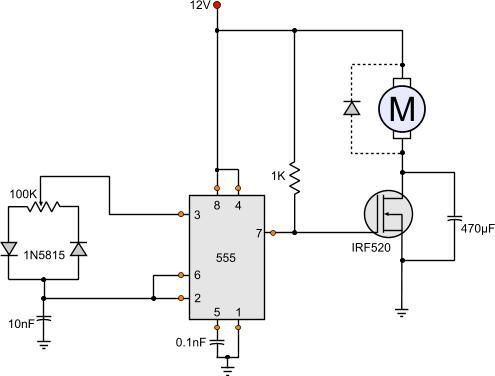
Electrical Page Dc Motor Control Circuit Diagram Circuit Diagram Electrical Circuit Diagram Electronic Circuit Design
Electrical Page Dc Motor Control Circuit Diagram Electronic Design Pj Trailer Gooseneck Wiring 4 Pin Female Connector
12 Volt Dc Motor Speed Controller Circuit Diagram Motor Speed Circuit

12 Volt Dc Motor Speed Controller Circuit Diagram 3 Light Switch Led 230v

Dc Motor Braking Circuit Diagram Elec Eng World Circuit Diagram Electrical Motors Circuit
Dc Motor Braking Circuit Diagram Elec Eng World Electrical Motors Dimmer Switch Back Box 1996 Nissan Sentra Ignition Wiring
Pin On Electronics

Pin On Electronics 2 Phase Light Switch 2002 Honda Odyssey Radio Wiring Diagram

Pin On Electronics Circuit

Pin On Electronics Circuit 4 Prong Rocker Switch Wiring Way Trailer Plug Adapter

How To Build A Simple Pwm Dc Motor Speed Controller Using Atmega8 Microcontroller Mosfet And Pot Youtube Motor Speed Microcontrollers Circuit Diagram

How To Build A Simple Pwm Dc Motor Speed Controller Using Atmega8 Microcontroller Mosfet And Pot Youtube Microcontrollers Circuit Diagram Camper Trailer Battery Wiring Abb Dol Starter

How To Build A Simple Pwm Dc Motor Speed Controller Using Atmega8 Microcontroller Mosfet And Pot Youtube Motor Speed Microcontrollers Circuit Diagram

Connect the motor to a dc power supply.

Dc motor circuit diagram. These devices link to the dc motor has these 4 main purposes. Simplest dc motor circuit. Self excited dc motor.

Charge builds up on what. Circuit components 9v power supply. On the other hand when the wiper arm of vr1 is at the bottom position c1 charges through r1 r2 and vr1 and discharges via r2.

In4148 or in4047 x 2. The pot here is used to adjust the speed of motor. The user can experiment with it for a right one.

100k 220k preset or pot. For the accurate operation of dc motor there must be some controlling circuit and protective devices are required to link with it to operate. When voltage is applied current flows from power supply terminals through the series winding and armature winding.

5v i inductive behavior of the motor causes current to continue to flow when the switch is opened suddenly. The dc shunt motor circuit diagram is shown below and the flow of current and voltage being supplied to the motor from the supply can be given by itotal e. When the wiper arm of potmeter vr1 is in top position capacitor c1 charges through r1 r2 and d1 and produces a pulse train at the output of ic1 with long negative and short positive pulse widths.

The circuit diagram of the proposed dc motor speed controller can be seen below. So let s get started with dc motor starters and circuit diagram. Therefore the motor speed is slow.

Free Electronics Circuits에 있는 핀
555 Dc Motor Speed Control Circuit Diagram Motor Speed Circuit

555 Dc Motor Speed Control Circuit Diagram Dometic Rv Air Conditioner Wiring 5 Point Relay

Arduino And L298n Circuit Diagram Dc Motor Control Arduino Arduino Motor Arduino Projects
Arduino And L298n Circuit Diagram Dc Motor Control Projects Electrical Outlet Schematic 2 Prong Trailer Plug
Dc Motor Controller Circuit Diagram For Clockwise Anticlockwise Rotation Circuit Circuit Diagram Electronics Circuit
Dc Motor Controller Circuit Diagram For Clockwise Anticlockwise Rotation Electronics Sylvania Quicktronic Ballast Wiring Red Wire Dimmer Switch
Pin On Circuit
Pin On Circuit Goodman Furnace Thermostat Wiring Diagram Marine Switch Panel
Interfacing Dc Motor To 8051 Microcontroller Using At89s51 Circuit Components Microcontrollers Interfacing
Interfacing Dc Motor To 8051 Microcontroller Using At89s51 Circuit Components Microcontrollers 240 Volt Breaker Three Phase Oil Starter Connection
Motor Speed Controller Circuit Diagram Proyectos Electronicos Electronica Circuito Electronico

Motor Speed Controller Circuit Diagram Proyectos Electronicos Electronica Circuito Electronico Understanding 3 Way Switches 4 Prong Plug Wiring

Pin On Electronics Electric
Pin On Electronics Electric 4 Wire Fan Motor Wiring Diagram Potential Relay
Pin On Electronique
Pin On Electronique 2 Way 3 Switch Position Toggle Off Wiring Diagram