Exemplary Ac And Dc Motor Diagram

Dc Train Motors Electrical Wiring Diagram 2002 Chevy Avalanche Radio Basic

Chapter 3 Ac And Dc Motors Induction Motor Engineering360 Electrical Diagram 7 Pin Female To 4 Male Trailer Adapter Cat6 Pinout

Bodine Electric Motor Wiring In 2020 General Capacitors Ground Diagram Wire Two Gfci Outlets Series

Chapter 3 Ac And Dc Motors Induction Motor Engineering360 Electronic Engineering Micro Usb Female Wiring Diagram Round Rocker Switch

Dc Motor Braking Circuit Diagram Elec Eng World Electrical Motors Static Transfer Switch 3 Phase Generator

Dayton Electric Motors Wiring Diagram Download In 2020 Electrical Circuit Chart Lutron Three Way Switch Pass And Seymour Double Pole

Power flow diagram of dc generator and dc motor the power flow diagram is used to determine the efficiency of a generator or motor.
Ac and dc motor diagram. In the above difference between dc and ac generator several higher level concepts are also included to give in depth insights about the dc and ac generators. The transformer is used to step down the 230v ac to 13v ac. Difference between ac and dc motor the ac motor and the dc motor are differentiated on the various factors like the source or the nature of the power used in the motor.
Another important difference between ac and dc is the magnitude of the voltage. In this motor field as well as stator windings are coupled in series by each other. And supplied with dc to create fixed polarity poles.
These were the main ac and dc generator differences. Accordingly the armature and field current are equivalent. A dc motor is any of a class of rotary electrical motors that converts direct current electrical energy into mechanical energy.
This by the way is exactly how a synchronous ac motor works. Ac drives also known as vfd convert the ac supply to dc using converter rectifier and invert it back from the dc to the ac using inverter to run the ac motors. The most common types rely on the forces produced by magnetic fields.
Generally copper bars form. In the below figure of power flow diagram of dc generator it is shown that initially the mechanical power is given as an input which is converted into electrical power and the output is obtained in the form of electrical power. Huge current supply straightly from the supply toward the field windings.
1n4007 has a peak repetitive reverse voltage of. Dc generators power very large electric motors like those needed for subway systems. Basic operation of ac motor stators and rotors with ac motor diagrams.

Ac Motor Sketch Google Search Electrical Diagram Induction Home Light Switch No Neutral Led Circuit 230v

Pin On Electric Testing And Repair Rocker Switch 5 Wiring Diagram Fuse Symbol

Introduction To Dc Circuits Electric Voltage And Current Alternating Circuit Wf 8955 Wiring Diagram Led Headlight

Ac Motor Speed Controller Circuit Electronic Projects Electronics Boat Trailer Light Wiring 2001 F350 Harness

How To Build A Simple Pwm Dc Motor Speed Controller Using Atmega8 Microcontroller Mosfet And Electronic Circuit Design Electrical Diagram Dim Lighting Trailer Brake Wiring Schematic Rocker Switch Led Always On

Single Phase Induction Motor Winding Diagram Electrical Circuit Capacitors Pole Switch With 3 Wires Metal Halide Wiring

Electrical Page Dc Motor Control Circuit Diagram Electronic Design Floatless Relay Room Wiring
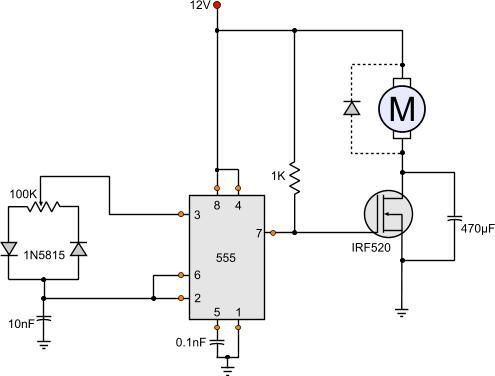
555 Dc Motor Speed Control Circuit Diagram Freightliner Cascadia Fuse Box Location 2 Way Light Switch
